Feb 07

What is inside a Samsung S7 smartphone?

This case study is a quick but powerful demo of what X-ray CT inspection can do. The Samsung S7 used in the test is my own phone, 2 years old and not in use. This phone was released about the same time as the Samsung Galaxy Note 7 – which had battery explosions often. The S7 was also known to overheat (my own experience also), so let’s see what’s going on inside this phone.

edf

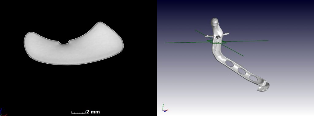
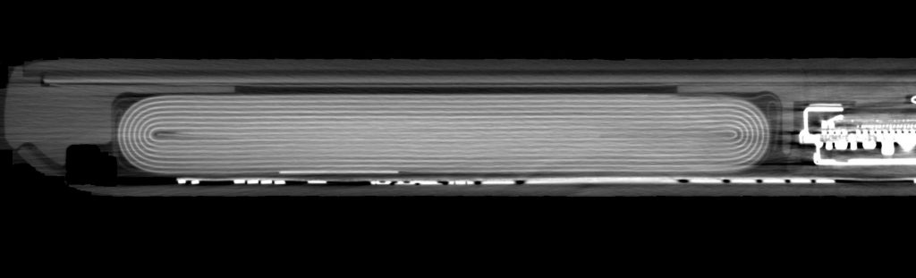
The top-view cross section of the battery shows its layers tightly wound up – the edges seem to be “compressed” into the tight-fitting space (top right for example). Seems like too much material for too small space, but no short circuits or flaws directly seen here.

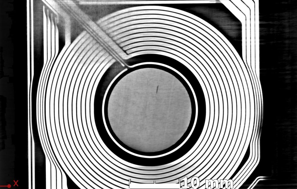
The only flaw found in this phone was a small indentation on the battery, behind the antenna (black stripe):

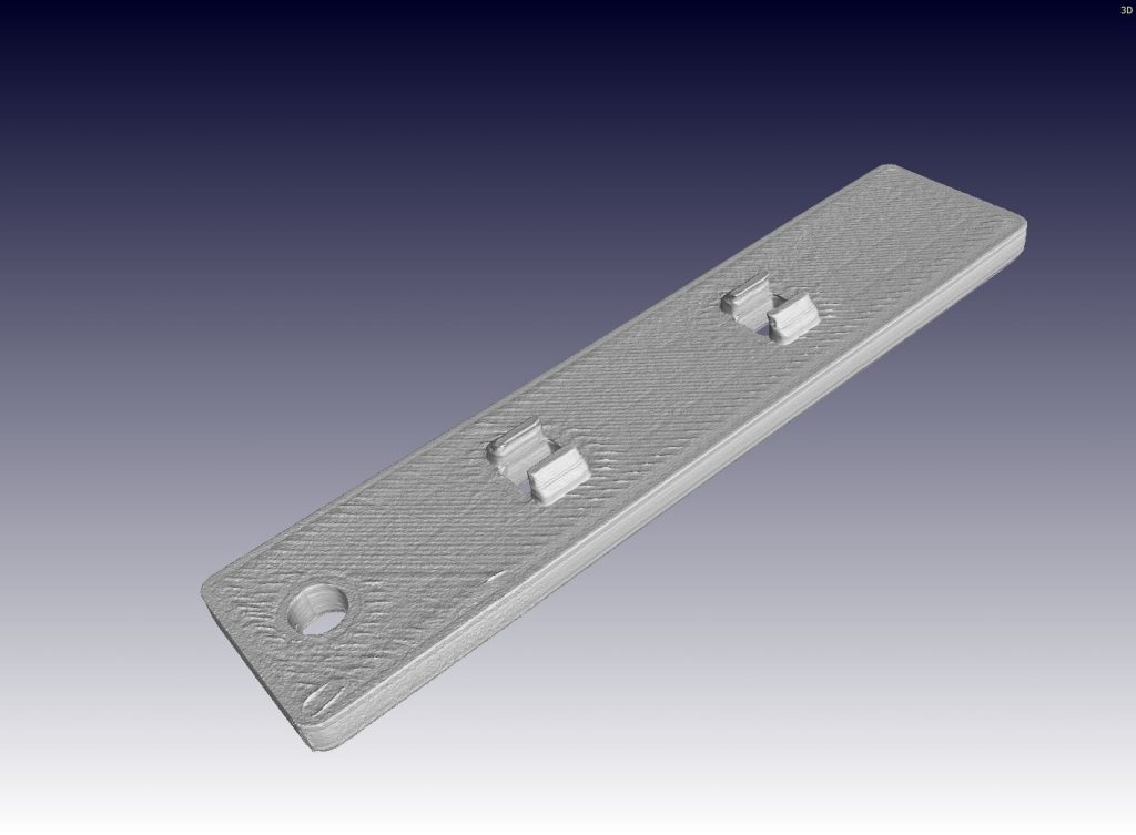
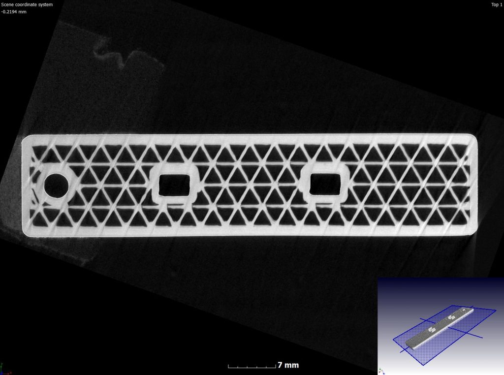
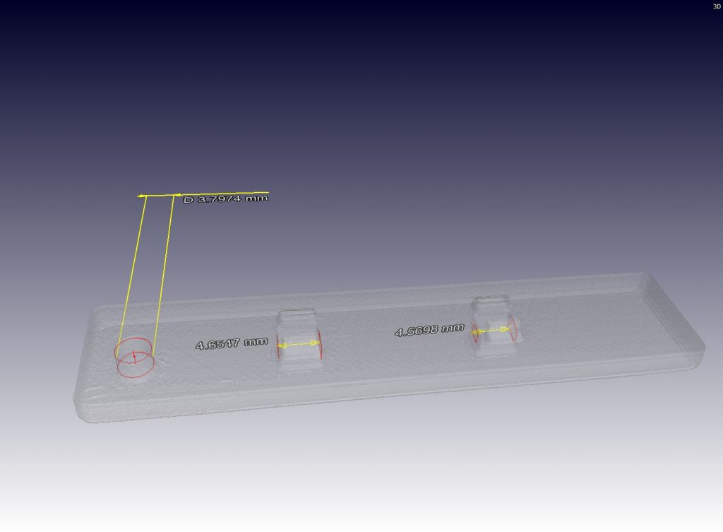
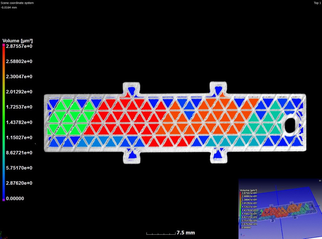
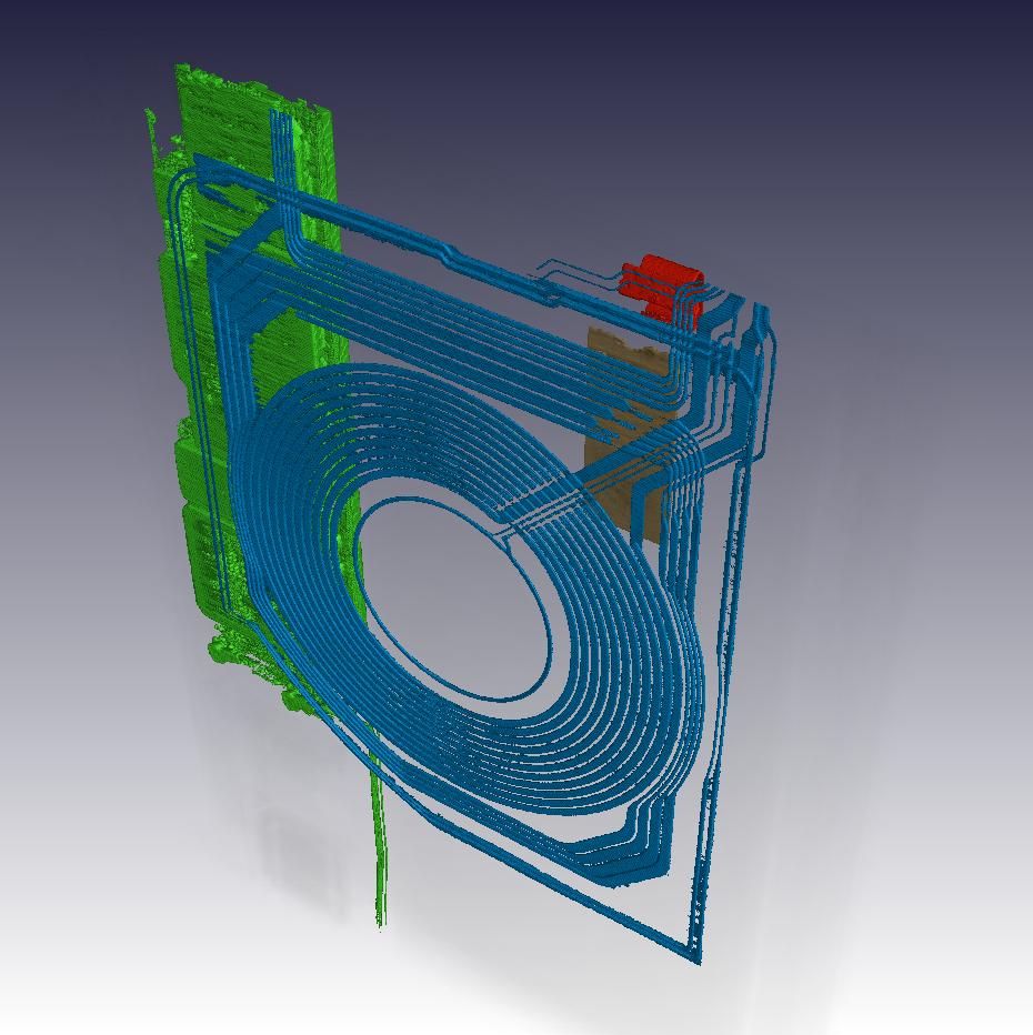
3D visuals helps to understand connectivity and orientation of different parts, for example this image shows some sections highlighted:

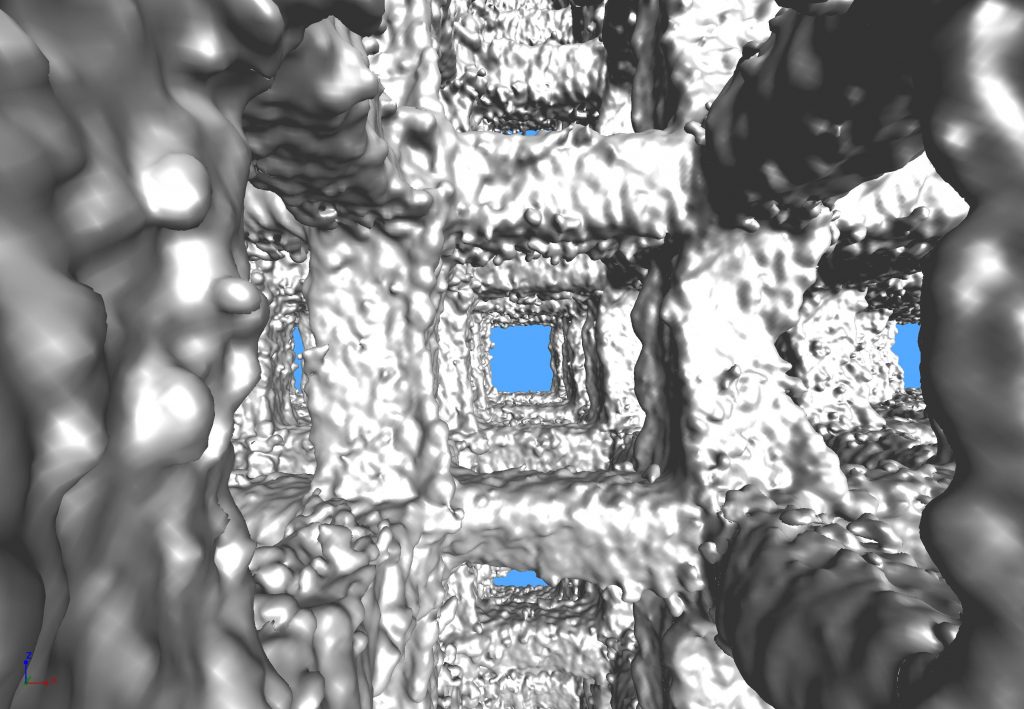
The following video shows the entire phone in 3D views of various internal sections, including inspection of electronics soldering pads – these always have some voids (air spaces) but they should not be too big, this one passes:

samsung vid3

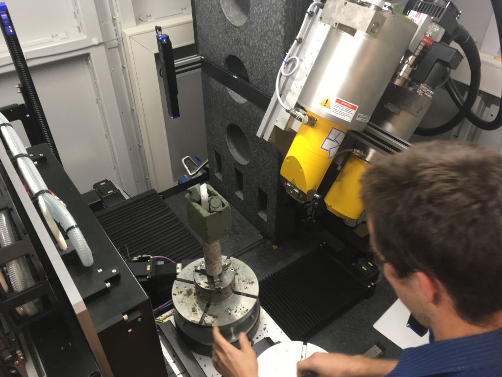
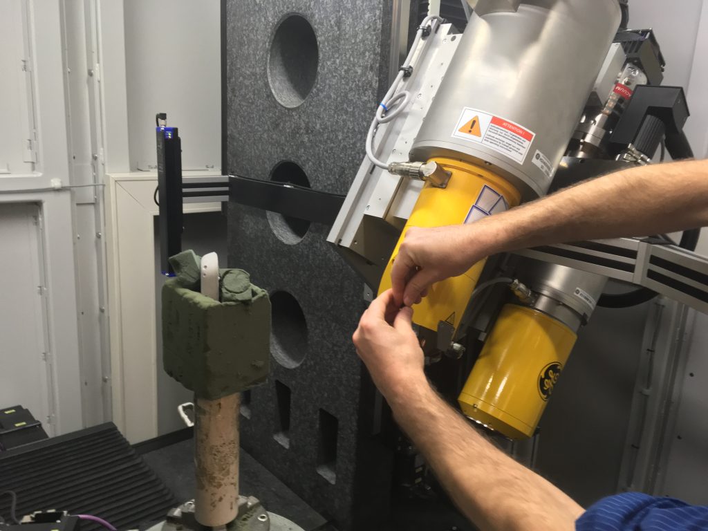
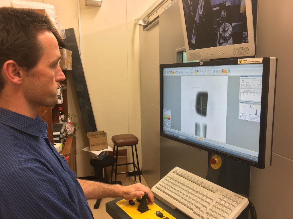
If you want to make a non-destructive test of your product, or want to apply this test to your research topic – contact us. This case study used an quick overview scan and a detailed high-resolution scan overlapped. Analysis by VGSTUDIO MAX 3.2.

Jan 17

Bike frame scanning

Here is a video of a recent scan, watch this space for more info!

bike NDT small video

Nov 01

View from the inside

This is a microCT image of the inside of a 3D printed metal lattice structure – the struts are 0.75 mm wide and rough as built by laser melting of metal powder.

Nov 01

Fully booked for 2018

Sorry but we are fully booked for the rest of 2018. We can still do surface scanning with our Artec scanners, and we can make image analysis or you can book for your own image analysis sessions, but scanning is not possible this year anymore.

If you have a super critical scan to be done, please contact us and we can make after hours scanning, if you drop off your sample.

For normal work, please book for 2019

Jan 25

New developments for 2018

With a new year comes new exciting capabilities and possibilities for our users. We have the following new additions to the facility, all becoming fully available on 1 Feb:

  1. New scanners: Artec Eva and Spider

Artec Eva and Spider are two scanners meant for 3D scanning of any objects to generate accurate surface models, including photorealistic texture. For more information on these scanners please see the Artec website:

Some ways you can use them for your R&D:

  • measure your fruit still growing on the plant, once a week, to check real growth and volume change
  • measure actual dimensions of large metal parts that are difficult for CT scans, to compare to design files
  • reverse engineer a complex part that is broken
  • scan objects and overlap 3D textured mesh with CT data of same object, for great visuals
  • scan weld seams to check for surface problems
  • scan your head to make a 3D print of yourself
  • and so much more!

2. Do your own scans

Many researchers and students want to do their own scanning, this is now possible, conditions are:

  • training charged at full rates for 8 hrs, one student per training only
  • student must pass a basic proficiency test after the training, or repeat the training
  • self-scanning is limited to fixed parameters set up prior to session
  • fixed after hours scan rate per evening session, irrespective of machine problems that might come up
  • currently only on nanoCT (samples smaller than approx 25 mm)

3. Make your own quotes online

  • system almost ready: starting 1 Feb
  • check the price for a scan, without any hassles
  • find a scan quality and service combination that fits your pocket
  • book your scans without any delays, any time of day!

Nov 10

Step by step microCT scan process

Here are some photos of a typical scan process, in photo steps:

Step 1: Load the sample in some low density mounting material – the sample is a concrete of undisclosed origin, and the project will not be discussed here
\

Step 2: load the sample into a rod or cylinder

Step 3: open the machine door

Step 4: load the mounted sample into the rotation stage of the machine


Step 5: Put in appropriate beam filter (that means a metal plate)

Step 6: Set up appropriate scan parameters (which might need some optimization per application)

Step 7: Start scanning

The next steps after scanning will be the focus of another day’s demo:

Step 8: Reconstruct the data

Step 9: Analyze the data – we use Volume Graphics

Step 10: Save the images, reports, raw data and copy to disk (we dont keep data here)

There is also a video on youtube: https://youtu.be/Yqui4OPVZu0
https://youtu.be/Yqui4OPVZu0

Aug 03

Metal casting analysis

Metal castings typically contain porosity which can affect the strength and lifetime of the part. Excessive porosity can be reduced by optimizing the casting parameters, and the best way to do this is to visualize and quantify defect sizes by X-ray microCT. It is also possible to routinely check castings to ensure nothing changes in your process, eg. you can select every 100th part and subject it to scanning. Of course we could also scan all your parts, the method is entirely non-destructive and therefore valuable for high-performance applications to make 100% sure there are no porosities present. Below are a series of images and videos demonstrating casting porosity analysis in two parts, both light metal alloys of 50 and 150 mm diameter.

This presentation in PDF has embedded videos, please view in Adobe and not in internet browser to see the videos (save to disk and open):
SG le Roux – Casting Presentation shorter3

In case the PDF file with embedded videos does not work, see below selected images and videos from these two casting examples:

Casting microCT scan – x-rays

casting slice video

Rotation 1

Rotation 2

Rotation 3

Rotation 4

Aug 02

Medical implant testing

X-ray microCT is nondestructive and therefore is used for testing produced parts for porosity or inclusions (defects) and sometimes for wall thickness or deviation from CAD design. All these types of analysis can be used to assess a part before implanting it into a patient. We provided this service for a recent implant patient who received an additive manufactured jawbone implant. This story once again shows the great advanced that are being made in additive manufacturing, and the combination with microCT technology is a great match. This story was aired on Carte Blanche, and can be watched here (which is not for sensitive viewers):
https://carteblanche.dstv.com/3d-face-implants/

The images and analysis of this implant is shown here (also two videos):

Video downloads for CT analysis of this implant:

no defects found

implant wall thickness
rotation 2

Aug 02

Analysis of 3D printed parts

This example shows a typical microCT analysis of 3D printed parts. 3D printing and additive manufacturing technologies differ widely and quality control of these parts are very important. In this example, Markforged parts were scanned of the following types:
1. Nylon
2. Short fibres in onyx plastic
3. Long fibres in nylon

Here is a typical surface view of the nylon part, from which a STL file can be produced of the actual part.

This is the cross-sectional view of the part, viewing the interior cavities and which can be used to assess possible build imperfections:

This is a closeup of the same scan data:

A typical microCT scan comprises of slice images across the part, this slice video gives a good idea of the method of assessing a part from slice images:
slice video

MicroCT allows dimensional measurements, such as measurement of critical hole diameters or distances. It is effectively a coordinate measurement device, when using appropriate scan quality and appropriate software (we use VGStudioMax 3.0 with the coordinate measurement module). This is an example of some measurements on this part:

And a video demonstrating the same: nylon Cordinate measurement

In addition, other routine measurement types are possible, in this case the wall thickness analysis allows measurement of the walls inside the part, see the image below:

Defect or porosity analysis is usually applied to find small unwanted pores, in this case the large cavities could be highlighted using this method:
nylon defect analysis

The second part, which contains short fibres to increase its strength properties is shown here:

The cavities could be visualized in this part as well:

And some nice images, showing how microCT can not only be used for analysis but also for marketing:


The third part is very similar but contains longer fibres for higher strength. The slice image is shown below:

Here is a video combining the three scans, and virtually putting the I-beam together: Combined

For more information on microCT analysis of 3D printed and additive manufactured parts, please see some articles below:
http://online.liebertpub.com/doi/abs/10.1089/3dp.2016.0012
http://online.liebertpub.com/doi/abs/10.1089/3dp.2015.0034
http://online.liebertpub.com/doi/abs/10.1089/3dp.2015.0015