[:en]
Software
Discrete Element Method
The group uses the latest version of PFC3D, commercial DEM software by Itasca (www.itascacg.com). The software includes a thermal package for analysing heat conduction. The software was successfully used by this group in a wide range of research projects since 1998. The group has an in-depth knowledge and expertise in the use of DEM software to analyse complex granular flow and bulk materials handling systems as well as the development and implementation of user-defined contact models. The group is also familiar with the use of Rocky DEM.
Automatic Sphere-Clump Generator
ASG3D, Automatic Sphere-Clump Generator (www.cogency.co.za/software), for generating multi-sphere particles for PFC3D and EDEM based on 3D scanned models.
Particle Image Velocimetry
Particle Image Velocimetry (PIV) code (Matlab) is used together with high speed images to analyse material flow and to calculate the velocity fields.
Material Point Method
The group developed an in-house Material Point Method (MPM) computer code. This code, based on a meshless finite element method, can model applications where large deformation and displacements are present. It has been successfully used to model anchor pull-out and excavator bucket filling.
Equipment & Test Facilities
Calibration equipment
One of the group’s main focus areas the past 10 years was the design of specialised equipment to measure the properties of granular materials and the development of methods to calibrate DEM parameters. A number of articles on this work were published in leading scientific journals. The equipment was designed to handle material with particles up to 45mm in size. Calibration equipment include the following:
- Vibrating screen sorter for particle size distributions with a range of 5 mm to 40 mm in nominal size.
- 3D Laser scanner for scanning individual particles to obtain the shape in a format that can be imported into CAD or directly into DEM software.
- Confined compression tests (diameter up to 590 mm for measuring the bulk stiffness of material (particles up to 45 mm in size).
- Large shear box (diameter of 590 mm) for measuring the material internal friction angle, angle of dilation and the material-interface coefficient of friction (particles up to 45 mm in size, normal loads up to 70 kPa and 3.5 kN of shear force).
- Standard shear box (60 mm x 60 mm).
- Annulus ring shear tester (diameters of 260 mm and 138 mm) for measuring the internal friction angle and angle of dilation of materials with particle sizes up to 20 mm (normal load up to 70 kPa).
- Tribometer for measuring particle-interface and particle-particle static and dynamic coefficients of friction.
- Inclined plane tester for measuring the particle-interface static coefficient of friction.
- Two rotating drums for measuring the dynamic angle of repose. The one drum is 1000 mm in diameter and has a length of 500 mm and can accommodate particles up to 60 mmin size. The second drum has a diameter of 500 mm and a length of 350 mm.
- Slump tester (split cylinder) for accurate and consistent measurement of the static angle of repose (particle up to 45 mm in size).
- Sand box for the measurement of various angles of repose under different conditions (particles up to 20 mm in size).
- Pendulum device for measuring particle-particle and particle-wall stiffness and coefficient of restitution (contact damping).
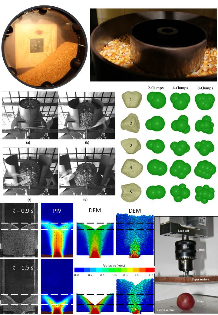
Calibration of DEM parameters from the top left to right: the dynamic angle of repose in the rotating drum, the annular shear cell, the static angle of repose measured in the slump tester, 3D scanned particles and the equivalent multi-sphere particles, validation of parameter values using PIV data, measuring the stiffness of a grape berry.
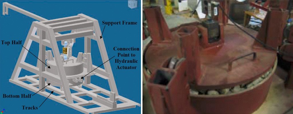
Large scale shear tester.
Other equipment
- High speed cameras (up to 10 000 frames per second) for observation of various flow processes and single impacts.
- An array of force, torque and displacement transducers.
- Data acquisition systems.
Soil bin
- A 6 meter long sand bin with a moving trolley for attaching equipment/tools.
- Variable trolley speed.
- Forces and moments acting on tool can be measured.
- Mainly used for agricultural applications of soil-tool interaction such as ploughs and blades.
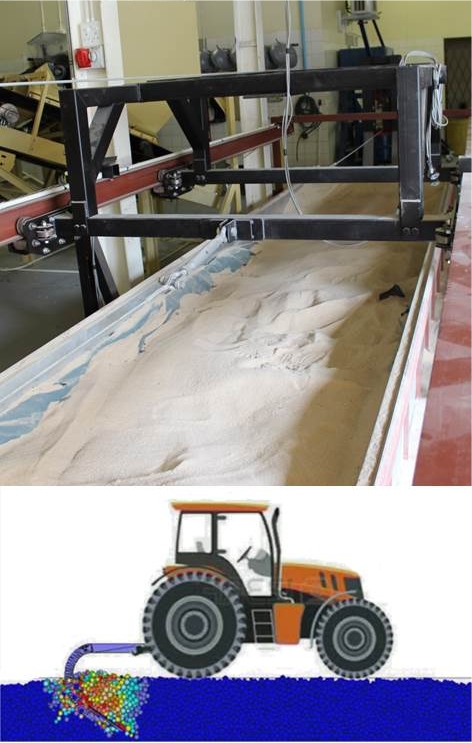
The 6 m long soil bin for testing soil-tool interaction and the DEM model of a plough tested in the soil bin.
Conveyor transfer test facility
This is a unique facility and one of only a handful instrumented test facilities world wide. The facility can be used to experimentally test various designs of conveyor transfer chutes. It is also used to validate semi-empirical, analytical and continuum based design models (CEMA) often used by industry to design transfer points. DEM models are also validated by evaluating the accuracy with which it can predict the material flow rates, spillage, build-up inside the chute, blockage, wear, the loading profile on the receiving conveyor
(off-centre loading), material trajectories from the feeding conveyor through the whole chute and the impact velocities and angles with the receiving conveyor.
- Three conveyor belts together with two transfer chutes and a hopper form a continuous flow loop and there is no need for reloading of material.
- The belts are 450 mm wide and up to 6 m long.
- The belt speed can be continuously varied between 0 m/s and 6 m/s.
- The transfer chutes can be up to 3 m high.
- Test facility is modular and the main transfer chute can be replaced by other designs for testing.
- The two hoppers have a storage capacity of 1.0 and 0.4 cubic meter respectively.
- High speed cameras are used to capture the material flow through the chute including the trajectory from the feeding conveyor and impact velocity vector on the receiving conveyor.
- The belts are equipped with load cells and belt weighers for mass flow measurements.
- This is used to determine the build-up rates in chutes and spillage rates.
- The belt speed and material feed rate are controlled by a PLC interface.
- Material flow rates (kg/s, t/h) on the conveyors and high speed camera images are easily recorded for analysis and post-processing.
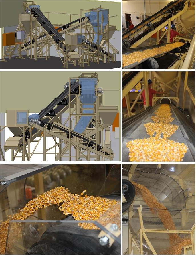
Conveyor transfer test facility: CAD models and experiments.