
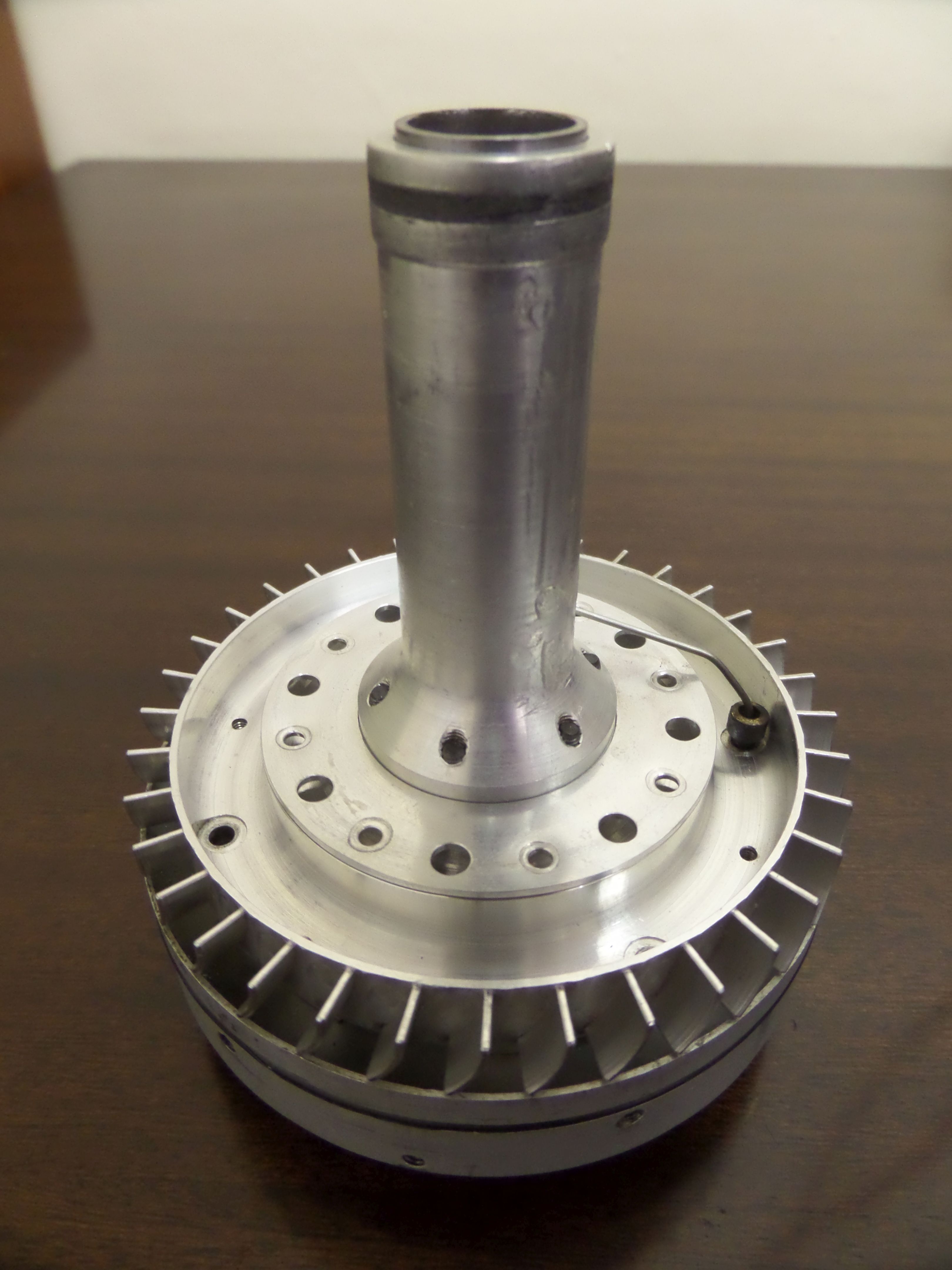
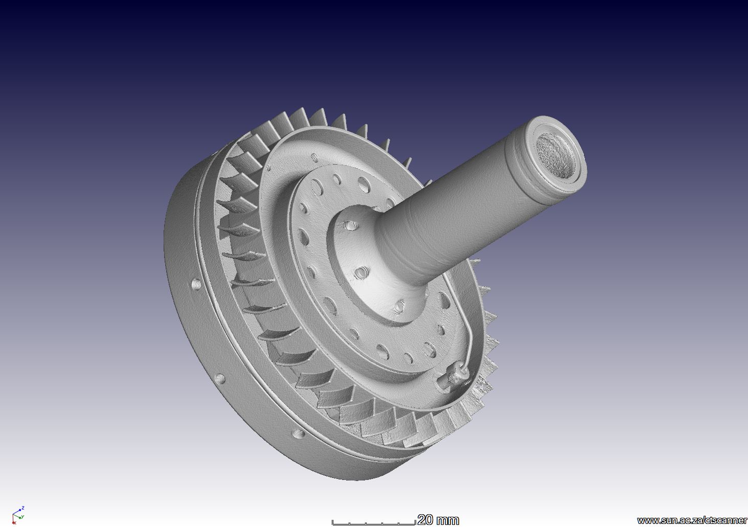
In this example a typical 3D X-ray analysis is presented of some radio-controlled airplane engine parts. Thanks to Clinton from Micton Hobbies in Somerset West, for loaning us the parts. Here are photos of the parts:
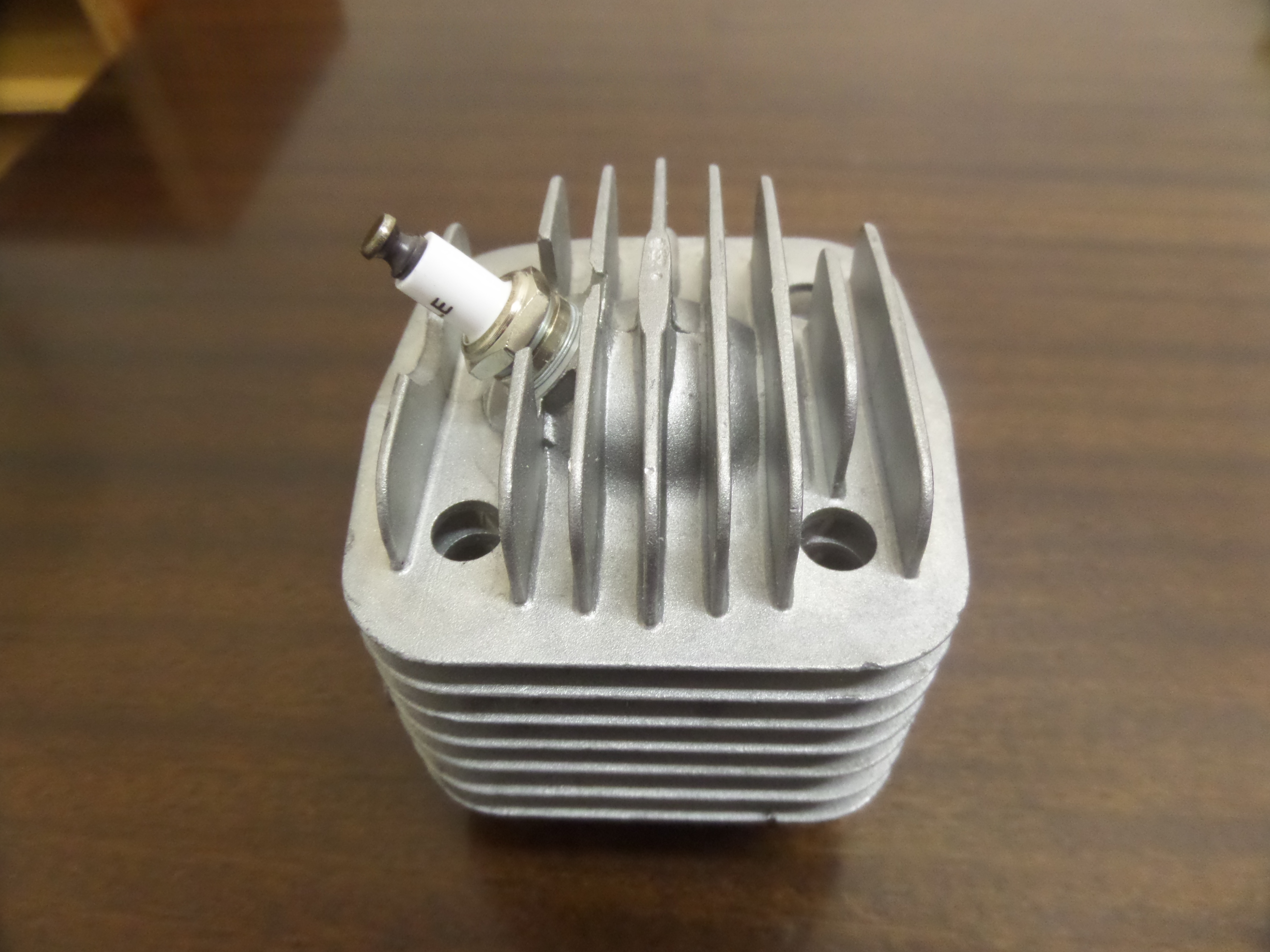
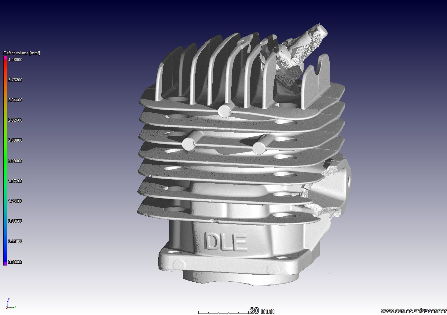
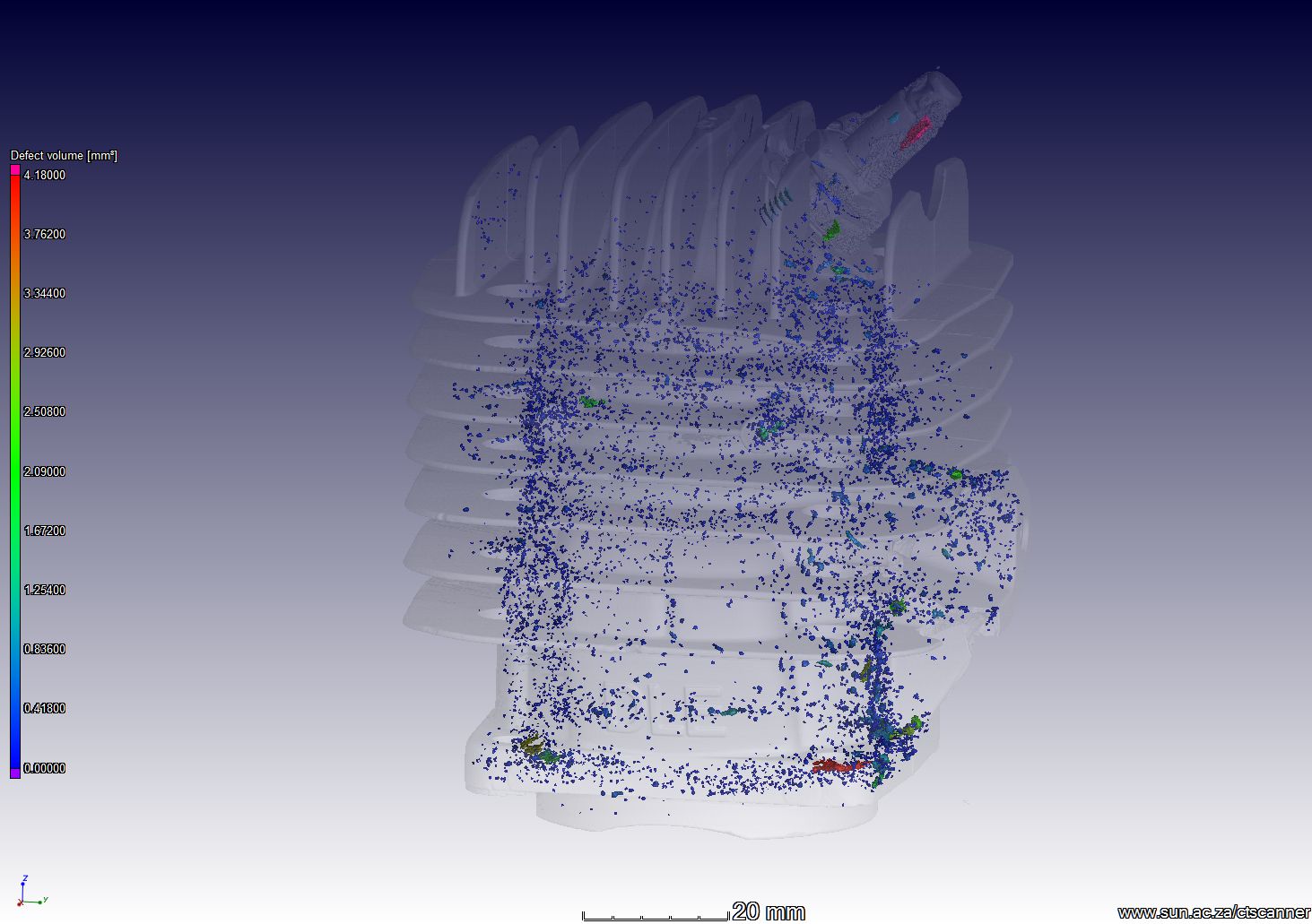
The engine casing is a light metal casting, containing pores/defects. The 3D images clearly show all the defects down to 0.1 mm diameter, while sorting the defects to only show those bigger than 1 mm simplifies things for easy viewing of problem areas. The 2D slice image videos shows the defects in more detail (black spots in the slice image video).

Video of defects in 3D: ROTATION VIDEO RC AIRPLANE ENGINE CASING DEFECTS
Video for iPad viewers: engine casing defect analysis
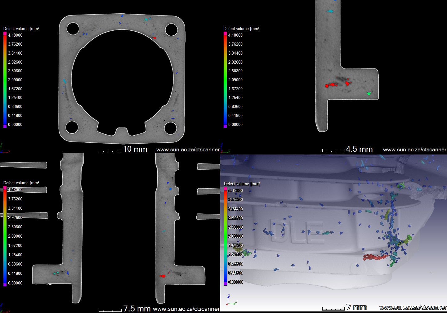
Slice video from top: slice video top view RC airplane
For IPAD viewers: slice movie top view
Slice video from side: slice video other side view rc airplane
Slice video from other side: slice video other side view rc airplane
For iPAD viewers: slice video engine casing
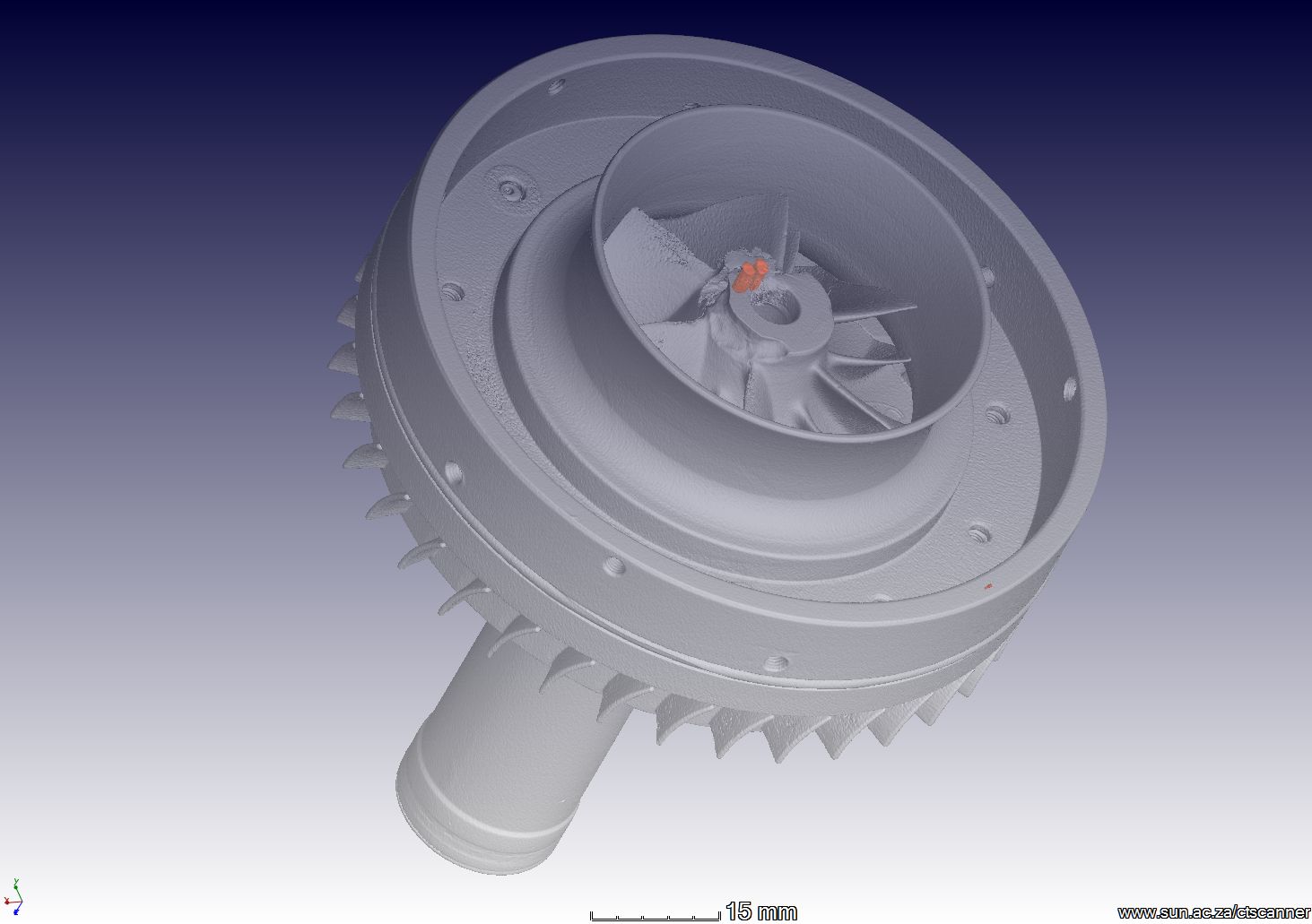
The rotor assembly results are shown below. No porosity is found at all, indicating the part is not a casting. Angular deviation of the central rod can indicate possible problems. In this example, different materials are coloured in differently, and two metal inserts for balancing the blades are highlighted as well (their positions where not known before).
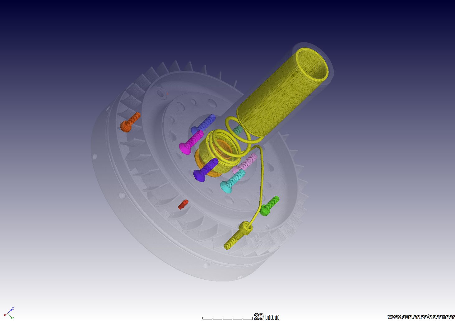

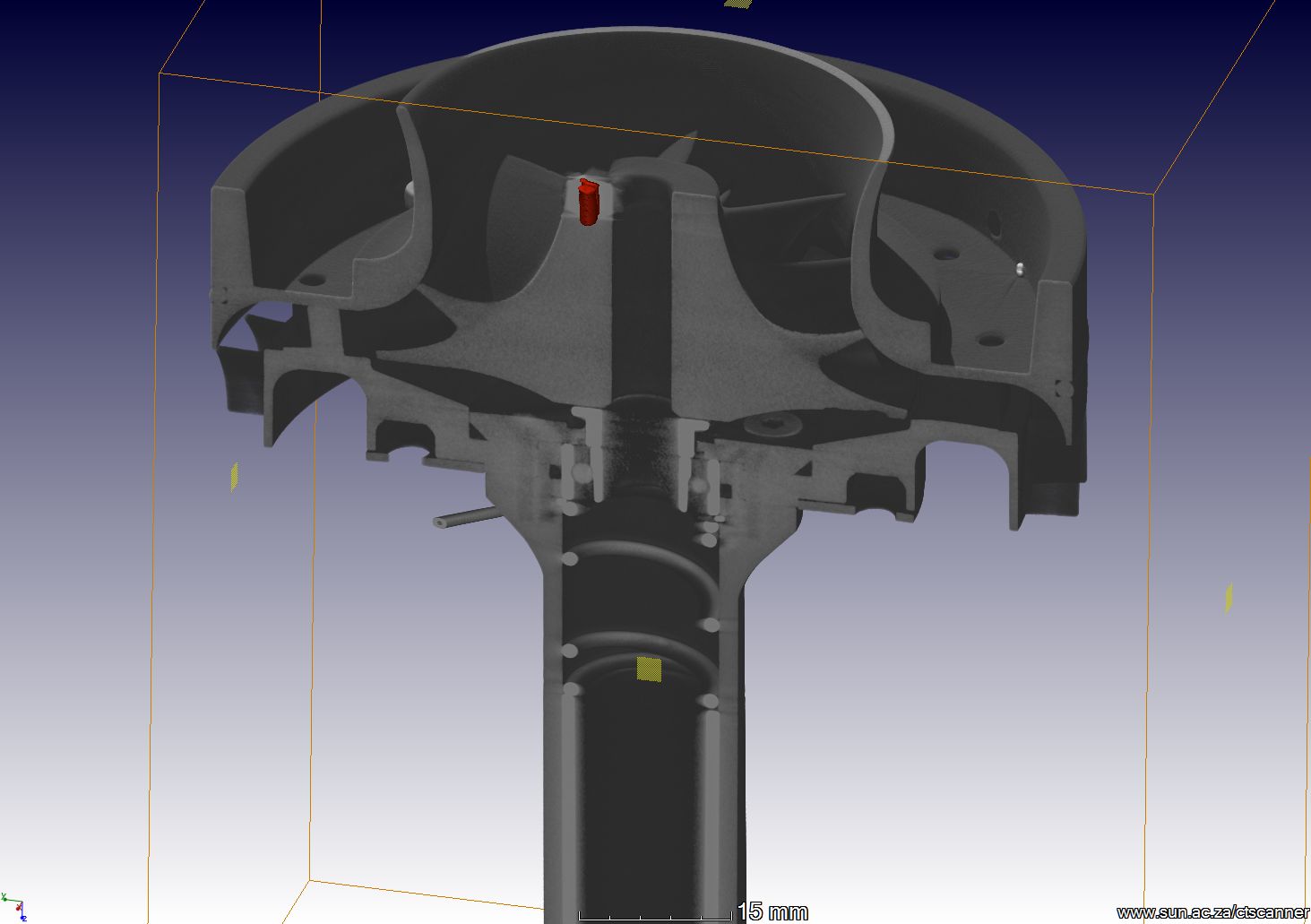
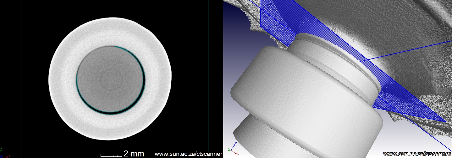
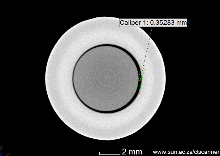
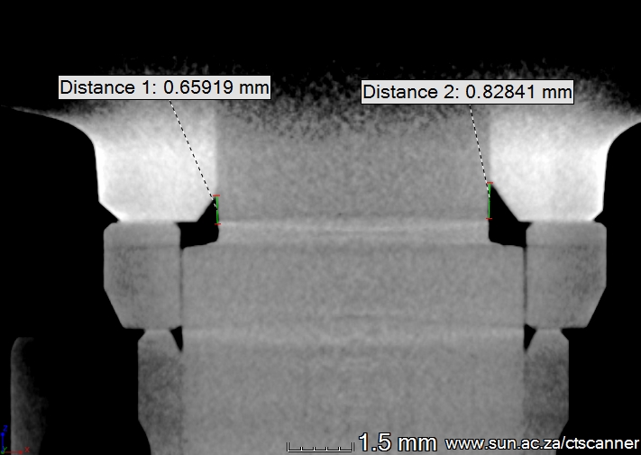
Images showing the central axle is not perfectly centre (at a slight angle and off-centre):
Video of rotor assembly: ROTOR VIDEO1
Video of a different turbine blade assembly from the same engine including wall thickness analysis and highlighting small cracks: turbine blades
Analysis performed in VGStudioMax 2.2
 Follow